Facilities
 |
Beam-Down Solar Thermal Concentrator (BDSTC)This is a point focus concentrator of around 280 m2 of primary reflective area. The primary reflector system comprises of 33 2-axis tracking heliostats. This 100 kWth solar thermal concentrator is a unique solar research facility. As opposed to conventional tower plants, the receiver is located at the lower focal point close to ground.
|
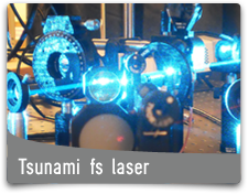 |
Tsunami fs laserThe Tsunami® mode-locked Ti:Sapphire laser provides fs pulses with a broad wavelength range and high power levels.
|
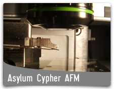 |
Asylum Research Cypher Atomic Force Microscope
Click here to read more... |
 |
Asylum Research MFP-3D AFM
Click here to read more... |
 |
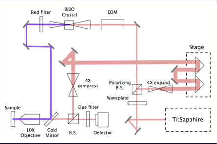
Pump ProbeThe Pump-Probe technique is an optical technique for determining the thermal properties of thin films. The setup is illustrated in the picture. We use a pulsing laser that emits laser pulses of 800nm wavelength at a frequency of 80MHz. The laser beam gets split into two beams: pump and probe. The pump beam is modulated through an electro-optic modulator and then undergoes a second harmonic generation that doubles its frequency.
Click here to read more... |